Figure 1: Optical diagram of PISCO.
Speckle observations require a large magnification, a narrow observing bandpass --up to a hundred nm wide-- and a correction for the atmospheric chromatic dispersion (see Roddier, 1981). The camera we have built satisfies these basic requirements and its general layout is shown in Fig. 1 and Fig. 2.
The input image plane (I1) of the telescope Cassegrain focus is located 200 mm downstream from the front flange of PISCO.
The converging input beam is transformed into a parallel beam by the collimating lens (L2), then focused into the image plane (I2) by the lens (L3).
Lens (L4) magnifies this image and projects it to the detector
faceplate. The focal length of (L4) can be selected with the wheel GR
that bears a series of eyepieces and microscope objectives. A high
magnification is needed to obtain a good sampling
for speckle observations (i.e., at least 20 mas/pixel
for the 2-meter TBL, since the diffraction limit ![]() is 40 mas at
is 40 mas at
![]() 400 nm) while a lower magnification is used for field acquisition.
400 nm) while a lower magnification is used for field acquisition.
Filters allow to select the desired wavelength range and neutral densities are used to adjust the light level to the (generally poor) dynamic range of the photon-counting detectors. The atmospheric dispersion is corrected with a set of Risley prisms (Breckinridge et al. 1979). These prisms can be rotated to produce a tunable chromatic dispersion both in amplitude and direction. They are remotely controlled by a PC which computes the atmospheric dispersion using a model of atmosphere (cf., §2.2) The Risley prisms are dynamically adjusted during data acquisition to yield a dispersion residual negligible compared to the diffraction limit of the telescope.
The filters, the neutral densities and the Risley prisms are located along the parallel beam, between the (L2) and (L3) collimating lenses.

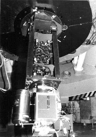
Figure 2: PISCO at the Cassegrain focus
and photo-counting detector CP40 at the TBL.
Compared to other speckle cameras (Blazit et al., 1977, Breckinridge et al. 1979, Strittmater, 1980, Foy, 1988a) our instrument has a few characteristics of its own. When a field lens (L1) is selected in wheel CH, the pupil plane is accessible and pupil masks can be placed for coronagraphy (§3.3) or multi-aperture interferometry (§3.2). A grism can be selected in the filter wheel FA in the parallel beam, for low dispersion spectroscopy (§3.4). Wavefront analysis is also possible with an Hartman sensor (§3.5). After an extensive testing of the classical full aperture speckle imaging characteristics of our instrument, the possibilities offered by these less common operating modes will be explored in a second phase of our program.
PISCO can be seen as an optical bench on which
mounts and wheels can freely move and be put at fixed
positions. This concept allows a great flexibility for future instrumental
developments.
The external mechanical structure is a rectangular box of
100 ![]() 40
40 ![]() 36 cm
36 cm ![]() . All instrumental functions,
including wheel positioning and angular control of the Risley prisms, are
monitored by a microprocessor and remotely accessible via a RS232 link.
. All instrumental functions,
including wheel positioning and angular control of the Risley prisms, are
monitored by a microprocessor and remotely accessible via a RS232 link.
One of us (J.-L. Prieur) has developed a program in the Window environment to facilitate the remote control of PISCO. All the basic functions are available (Fig. 3) such as the control of the automatic atmospheric dispersion correction according to the telescope position, the filter and the atmosphere parameters (§2.2). A log file is also produced at the end of each night with the PISCO parameters of all the exposures taken during that night.
Figure 3: Main panel of the program which controls the speckle camera PISCO.
PISCO was primarily designed to be used at the Cassegrain focus of TBL, but it has also been made mechanically and optically compatible with the Cassegrain foci of the Canada-France-Hawaii (CFH) and European Southern Observatory (ESO) 3.6-m telescopes.